

2026 Q2 Review - Hatchback
Updated: Jul 3
Picking up where we left off, it was time to join the 90 degree turbo exit pipe to the Invidia 3 inch downpipe. What seemed to be a simple task, however, turned to hours of refitting, adjusting, marking and cutting a cardboard template, and eventually shaping a section of 3 inch stainless steel tube to join both the turbo exit to the downpipe, which joins to the rear exhaust section. The joiner tube was marked on both sides when fitted, and the three pipes were welded together.

Mercifully the new downpipe just about cleared the engine bay bulkhead, although this and the brake servo were later covered with Funk Motorsport gold tape in attempt to deflect radiant heat from the downpipe away from these areas.

Due to the turbo's higher position, the clutch reservoir drain plug fouled against the new downpipe. For some reason this is a large disk with a M16x1.5mm thread, rather than a smaller style plug. Fortunately, our good friend TC Works (@homebrewMR2 is his Instagram handle) kindly ground down a Honda motorcycle bar end which had the same thread and helped to bleed the clutch line.


When it came to fitting the rest of the exhaust, however, the downpipe did not meet the rear section! Thankfully, a cardboard template, the bandsaw, and the TIG expedited making a short joiner piece for the pipes to meet, allowing the full exhaust system to be fitted.

Another task was to mount the coolant reservoir, which originally mounts on the factory intake manifold, but required a separate mount due to the new Process West intake manifold. This was again time for a cardboard template and to break out the TIG. A single piece construction was attempted, which used captive nuts for the existing bolt holes, and a stay for the coolant tank's locator. Although not perfectly level when installed, we will report back on how the bracket fares this year!

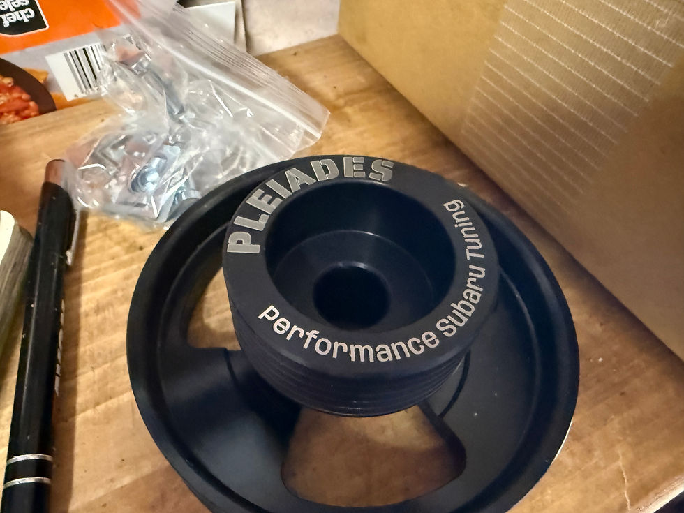
Another task was to fit the auxiliary belt, which transfers power from the engine crankshaft to the power steering pump and alternator (there's no space to run the AC compressor when using a rotated intake manifold). Trial and error enabled us to find the correct belt to use the IAG V2 alternator relocation kit, whereby the alternator is flipped upside down, which required extending the alternator's positive feed wire. It was important to use a high gauge wire here to minimise electrical resistance. The original alternator positive line connector was connected to the end of the extension wire, which was secured to the car's wiring harness.
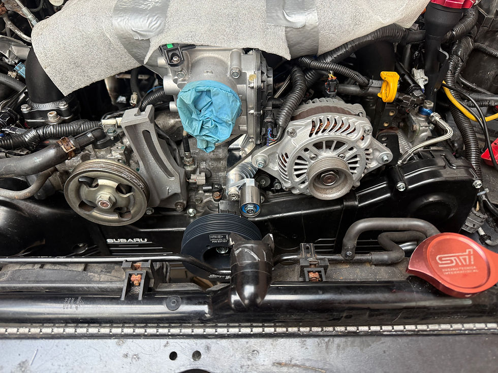
Next, it was time to fit our Samco radiator hoses which we purchased during the winter sales! Unfortunately we had purchased the incorrect kit (for earlier model Imprezas), but RCM were to the rescue and within a couple of days, the correct kit was fitted. The top hose was a bit of a stretch to fit, so a small aluminium coupler was put on the shopping list to extend the hose.


It was then time to delve into the world of aluminium welding, which turns out is quite a tricky business! The turbo outlet pipe to the intercooler hot side needed to be altered from its original size, due to the turbo's new position, and the intercooler cold side pipe also needed to be altered due to the new rotated intake manifold. A flexible 100m tube was used for the turbo intake, which was extremely awkward to fit, but provided the largest intake pipe size possible for the turbo.

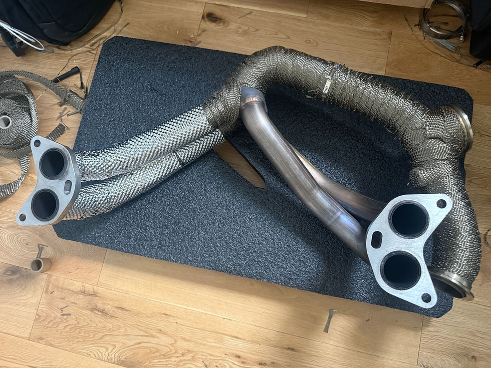
The bandsaw was used to ensure that the pipes were cut as cleanly as possible, and the pipes were marked once in position, and TIG welded together. As with the hillclimb car, it was important to control heat as much as possible within the hatchback's engine bay. After some thought, we took the plunge and wrapped the exhaust headers, turbo up-pipe, and turbo downpipe with Funk Motorsport heat wrap and covered the wrap with a thin stainless steel sheet spot welded together for added durability and to minimise dirt and water ingress.


A coolant pressure relocation kit and adapter was fitted to the coolant pressure sensor's standard location in the coolant crossover pipe. This allowed us to use a Bosch combined temperature and pressure sensor near the heater matrix coolant pipes. It was then time to fill the cooling system with a coolant cleaner and distilled water, to fit the RCM racing oil filter (which we also sell in our online store), and to fill the engine oil - we initially used Ravenol 10w 50. It was then time to start the engine and fix the inevitable leaks! After starting cleanly, the Link G4X presented an E-throttle error. As the throttle body's aluminium outer surface had been carefully vapour blasted but checked for movement prior to installation, it was feared that a new throttle body was required. Having removed the throttle body, the butterfly valve could not be moved at all! It turned out that some moisture had condensed within the throttle body (possibly from the vapour blasting process), which had jammed the servo motor. A liberal application of ACF-90 later and the butterfly valve moved as it should and the throttle body was refitted to the Process West intake manifold.

With no issues showing on the Link G4X, and some small fuel leaks sorted, it was time to take some tentative trips in the hatch to check all was ok. It was immediately apparent that the coolant relocation kit was unable to purge an air bubble near the sensor end, which caused the car to over fuel when the engine was warm, as the coolant sensor registered the ambient temperature instead of the coolant temperature. It also became apparent that the relocation kit caused a coolant system leak, which caused the coolant system to boil over (a slightly terrifying experience!).
With the original sensor used instead of the combined temp and pressure sensor, it was relocated to the oil pressure relocator kit. Again, the same problem occured, with the temperature sensor unable to measure the true oil temperature due to an air bubble, but the pressure sensor working correctly. Needless to say the relocation kit was removed and the oil gallery port (where the standard oil pressure switch is mounted) re-tapped for the Bosch combined sensor's M10x1.0 thread. With the temperature sensor reading correctly, this allowed us to set up an engine protection strategy in the Link G4X to bring in a lower rev limiter if the oil temperature was outside of its operating range. During our initial drives, the idle oil pressure seemed low at around 1 bar. This was increased to 1.3 bar following an oil change over to Motul 10w60.
Something which had been on the cards for a long time for the hatch was making a proper cold air intake. As with the other fabrication jobs, a cardboard template was made and transferred over to Aluminium sheet. Welding a piece to bridge the vertical and horizontal pieces was challenging to say the least, which was covered with aluminium tape and will be revisited at the end of the year.


A small aluminium panel was also used to cover a small gap near the exhaust headers to minimise the possibility of the hatch pulling in hot air from the engine bay!

As the air filter is located in the inner wheelarch, the offside fog light cover was altered to allow air into the wheelarch, and covered with a protective mesh to protect the air filter from any large debris. It was then time to map the hatch ready for its outings in Oulton Park and the Curborough Sprint Course at the end of June!


Comments